Written by Frank Duignan, Electronics Engineer and Lecturer at TU Dublin, Ireland
This blog originally ran on the Frank’s website at ioprog.com. For more content like this, click here.

Recently, we asked our students to buy BBC Microbits for our Internet of Things module. Most of them received version 2.0 of the board. Some however received version 2.21. The main difference between the boards is the USB interface MCU. Version 2.00 used an NXP MKL27Z256VFM4. The 2.21 version changed this to a Nordic Semiconductor NRF52820 device. In most cases, users will not notice the difference between the two boards. However, if you are programming hardware registers directly there are some differences. We use Zephyr OS in our IoT module and work at the hardware level so, for us, this showed up as missing interrupts from the LSM303 Accelerometer/Magnetometer.
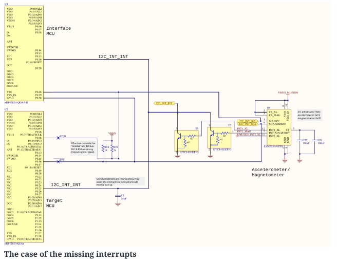
Our sample code programs the LSM303 as a step counter. When the accelerometer experiences low acceleration in all 3 axes (i.e. in freefall) it outputs an interrupt signal. This signal pulls the I2C_INT_INT line low (falling edge interrupt trigger). On Version 2.00 boards this worked fine, not so on V2.21 boards. The problem turned out to be that the interface MCU was holding the I2C_INT_INT line low permanently which prevented falling edge interrupts.
The solution
I contacted microbit.org and quickly received a response from Carlos. He pointed me at this site which documents the I2C interface protocol implemented by the interface MCU. This looks quite interesting and will need further exploration at a later date. Carlos suggest that I program the target to perform a dummy read of the interface MCU over the I2C bus. I tried this and it almost solved the problem. Just after programming or after pressing the reset button, the Microbit processed interrupts correctly. After a power on reset however interrupts did not take place. Again Carlos came to the rescue and suggested that I pause the target boot for 1 second before performing the dummy read. This time allows the interface MCU to complete boot up before the dummy read. The result? Interrupts were processed correctly!
The initialization code for the LSM303 motion sensor was modified as shown below:
[php]
static const struct device *i2c;
int lsm303_ll_begin()
{
int nack;
uint8_t device_id;
// Set up the I2C interface
i2c = device_get_binding("I2C_1");
if (i2c==NULL)
{
printk("Error acquiring i2c1 interface\n");
return -1;
}
// Fix for version 2.21 of the Microbit.
// This code resets the I2C_INT_INT signal coming out of the interface IC (DAPLink)
// There is an acknowledged bug in the firmware for this IC which leave the interrupt
// line asserted under certain conditions. This prevents the LSM303 from raising interrupts
// A dummy read of the interface IC (I2C address 0x70) deasserts this signal
// Thanks to Carlos in microbit for this help.
k_msleep(1000); // allow interface MCU complete booting before dummy read
uint8_t dummy_value[5];
nack=i2c_read(i2c,dummy_value,1,0×70);
printk("nack=%x\n",nack);
// Check to make sure the device is present by reading the WHO_AM_I register
nack = lsm303_ll_readRegister(0x0f,&device_id);
if (nack != 0)
{
printk("Error finding LSM303 on the I2C bus\n");
return -2;
}
else
{
printk("Found LSM303. WHO_AM_I = %d\n",device_id);
}
lsm303_ll_writeRegister(0x20,0x77); //wake up LSM303 (max speed, all accel channels)
lsm303_ll_writeRegister(0x23,0x08); //enable high resolution mode +/- 2g
return 0;
}
[/php]
Thanks to Carlos Pereira Atencio from the Microbit foundation for lots of help solving this problem.
Full schematics are available here:https://tech.microbit.org/hardware/schematic/