Written by Frank Duignan, Electronics Engineer and Lecturer at TU Dublin, Ireland
Note: all examples used in this tutorial can be found in full on github.
When should you use an operating system?
There is no simple answer here other than this : “When the value it provides is greater than the cost of learning and using it”.
Among the value offerings of operating systems is hardware abstraction, complex library support, communications protocols and security. Developing these features/libraries from scratch is error prone and time consuming. There is no doubt that you will bring a product to market faster by using a good existing OS and it is likely that your maintenance burden will be reduced. You may also find it easier to recruit developers for such an OS in contrast to using a home-grown solution. That said, using an OS, even a free one, is not cost free. You will have to set up a development environment, learn about it’s libraries and API’s and possibly live with a bigger memory footprint, I/O timing jitter, and a higher CPU load. This may then cause you to raise the hardware specification of your MCU. Elicia White, author of Embedded Systems advises that you should consider using an OS for your MCU project once you get into the realms of networking and/or USB. This application domain is IoT so we will take that advice and base our application on an existing embedded operating system.
Choosing an OS
Factors affecting your choice: Cost, Code size (Flash memory), RAM usage, Hardware support, ongoing support and updates, licensing, value added features such as integration with IoT services such as remote firmware update and messaging. In the case of the BBC Microbit V2 there are not that many options for an embedded OS. The MCU at the heart of the Microbit-V2 is an NRF52833 from Nordic semiconductors. Nordic provides a “binary blob” to manage the radio interface and other hardware elements (this is referred to as a soft-device). In many ways this resembles an operating system. Application developers link this blob with their code and interact with it using an API. Embedded operating systems on this platform also interact with the soft-device and provide an additional range of services. Embedded OS options for the NRF52833 include:
FreeRTOS, Zephyr, and Riot OS (there may be more). Of these Zephyr stood out as having a very active development community. It is licensed using the Apache 2.0 license which is quite permissive. Nordic Semiconductors also seem to be actively supporting this OS so for these reasons, Zephyr was chosen.
What is Zephyr?
Zephyr is a designed to run on microcontrollers with a limited amount of ROM, RAM and CPU resources. It targets a range of MCU cores including various ARM devices, Intel x86, RISC-V and ESP32. This means that application development skills you acquire on one hardware platform can be transferred to other devices.
When we use the phrase “Operating System” we may be inclined to think of desktop operating systems such as Windows, OS-X, Linux etc. Desktop OS’s allow you load and run programs dynamically. Embedded operating systems such as Zephyr do not work like this. The OS and application are compiled together into one single file which is programmed on the target device. When the system starts up, the OS is booted and your application runs. Typically, your application is the only one running on the target system (it may have multiple threads but that’s another story). In this sense, you can consider OS’s such as Zephyr to be like a library that you might link with your own code.
Setting up a working environment.
In order to build applications for Zephyr you need to set up a compiler, libraries, header files and a host of other tools. This environment is sometimes referred to as a toolchain. Detailed instructions for setting up Zephyr on your computer are available here: https://docs.zephyrproject.org/latest/getting_started/index.html
Note: At the end of the installation instructions you are told to test your toolchain and board by compiling a simple blinking LED example. This will not work with the Microbit-V2 as there is no “simple” user LED on the board. You can however build the hello world example as follows:
west build -p auto -b bbc_microbit_v2 samples/hello_world –pristine
The output from this program is sent to your PC using a built-in USB-Serial converter in the Microbit. On Linux this will appear as device /dev/ttyACM0 typically. On Windows this will appear as COM3 or similar. Run a dumb terminal application with a baud-rate of 115200bps, 8 data bits and no parity and you should hopefully see the output on you PC screen.
The BBC Microbit (V2) hardware

The Microbit V2 has a number of built-in peripherals that are accessible by the programmer. These are shown above. The LED matrix is a arranged in a 5 row by 5 column matrix with one GPIO (GPIO= General Purpose Input Output port) row pin supplying (sourcing) current and a GPIO column pin absorbing (sinking) current. There are also two push buttons which are pulled high via 10k resistors; when a button is pressed it pulls a GPIO pin low. The edge connector provides access to GPIO pins some of which are also used by the onboard peripherals. So, if you plan to use an edge connector pin be sure that it does not interfere with an onboard peripheral that you also intend to use.
The onboard LSM303AGR is a 3 axis accelerometer and 3 axis magnetometer. It is used for motion sensing. It is connected to the NRF52833 via an I2C bus (signals can be viewed on board test points)
Zephyr and I/O pins.
Zephyr uses the a system called devicetree to identify GPIO pins, I2C devices and other peripherals. It is quite confusing for beginners (like me) to use and makes extensive use of C macros. In an effort to avoid turning this into a tutorial on devicetree the example projects will make minimal use of devicetree and will instead use Zephyr API’s to access I/O where possible.
Making patterns on the LED matrix

The full code for this example is in the project led_matrix
The LED matrix is wired as shown above. The Input/Output list is as follows:
| SIGNAL | PORT | BIT | SOURCE/SINK |
|---|---|---|---|
| ROW1 | GPIO0 | 21 | Source |
| ROW2 | GPIO0 | 22 | Source |
| ROW3 | GPIO0 | 15 | Source |
| ROW4 | GPIO0 | 24 | Source |
| ROW5 | GPIO0 | 19 | Source |
| COL1 | GPIO0 | 28 | Sink |
| COL2 | GPIO0 | 11 | Sink |
| COL3 | GPIO0 | 31 | Sink |
| COL4 | GPIO1 | 5 | Sink |
| COL5 | GPIO0 | 30 | Sink |
All of these pins must be configured as outputs (because your program will set them high or low). The Source pins must be a High to light an LED and the Sink pins must be Low.
The matrix can be configured in code as follows:

The Zephyr API calls used are:
get_device_binding and gpio_pin_configure
The first of these get_device_binding returns a pointer to a Zephyr device structure. The behavior is similar to the file open function fopen in C. If the device can’t be found a null is returned otherwise you use the returned value for future operations on that device. The argument passed to get_device_binding is GPIO_0 (and later GPIO_1). This string is used to search the device tree and if a matching device label is found the function returns a pointer to it’s device structure. So the first few lines of matrix_begin retrieve pointers to the gpio0 and gpio1 devices.
The gpio_pin_configure function takes three arguments:
A pointer to the device structure for that GPIO port
The bit number being configured
The bit mode. In our case this is GPIO_OUTPUT . You could specify GPIO_INPUT for input pins. See https://docs.zephyrproject.org/latest/reference/peripherals/gpio.html for further information about port pin configuration options.
In order to make these GPIO pins go high or low you should call the gpio_pin_set function as shown in the following function:
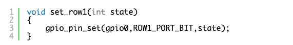
Once again, three arguments are required: you must tell it the port, the bit number and whether the pin is to be High (1) or Low (0).
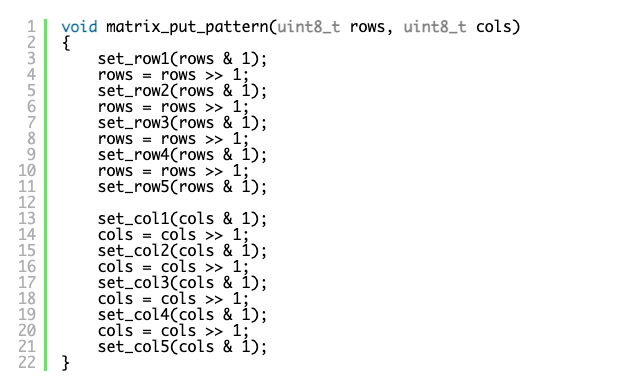
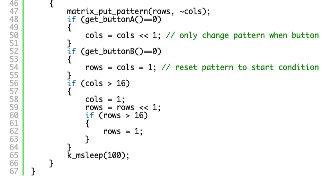
The function below can be used to put a pattern on the matrix. The row and column states are passed as the 5 least significant bits of the rows and cols parameters.
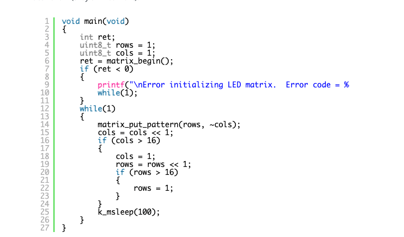
Finally, here is the main function that generates the matrix pattern. Note the inversion of the cols variable in the call to matrix_put_pattern. This is because column bits are active low (they sink current).
Other bits on the edge connector can be used in a similar way. For example looking at the extract from the Microbit V2 schematic below we can see that P2 or Ring 0 is connected to GPIO port 0, bit 2.

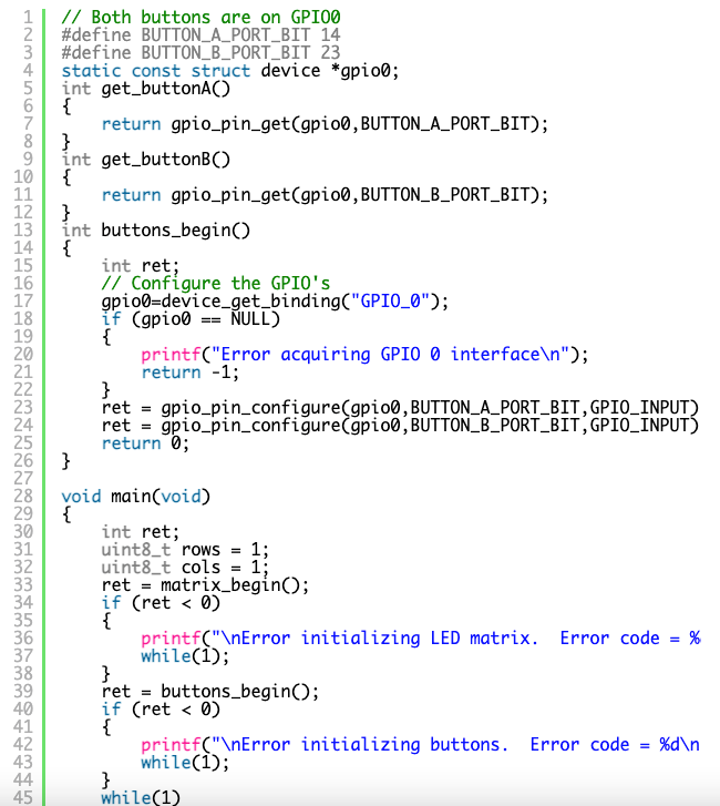
Reading inputs.
The Microbit has two push buttons that pull low when pushed. The configuration of these inputs follows the same pattern as the outputs above. First identify the port and bit number involved and use gpio_pin_configure to configure them as digital inputs (GPIO_INPUT). To read a pin state we call on gpio_pin_get passing two arguments: a pointer to the port device structure and the bit number in question. The function will return 0 or 1 depending on the pin state or and error code (negative value ) if something went wrong.
The full code for this example is in the project buttons_with_matrix
The above example uses “polling” i.e. continuous reading of the state of the inputs to decide what to do. This is inefficient as the CPU is running at full speed and may miss inputs if it is doing some other task. An alternative approach is to use interrupts which will trigger the execution of a particular function (the interrupt handler) when a hardware event occurs. If the CPU is busy doing something else this task will be suspended while the interrupt handler executes (so long as interrupts have been enabled. The example below is a modification of the above button code.

The function gpio_pin_interrupt_configure takes three arguments: a reference to the GPIO port, the bit number in question and a flag to indicate whether you want to be interrupted on falling or rising edges etc.
The function gpio_init_callback is used to prepare a structure of type gpio_callback which will be used in a follow-on call to the gpio_add_callback function. gpio_init_callback takes three arguments: the address of the structure that will be prepared, the address of the function that will handle the callback and bitmask identifying which pins will trigger the callback (note the difference between the third parameter here and the second parameter for gpio_pin_interrupt_configure).
The function gpio_add_callback is the last step in setting up interrupts. It takes two arguments : a reference to the GPIO port and the structure that was prepared by gpio_init_callback.
Following all of this, when a falling edge (a button press) happens the function button_a_handler will be called automatically. The declaration of this function is a little complex so I have decided to hide this from the typical user. Instead, the user calls on attach_callback_to_button_a and passes the address of a function they would like called when the button is pressed. This address is stored and when button_a_handler is activated it will call the user function there.
The main function matching this example is shown below.
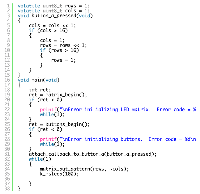
The full code for this example is in the project buttons_with_matrix_with_interrupts
Note the use call to attach_callback_to_button_a takes a single argument – the address of the function you would like to run. In this case, the callback function moves the led matrix pattern variables along a step each time the button is pressed. Also note the use of the volatile keyword.